The simplest circuit
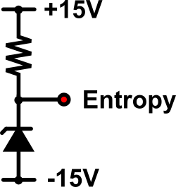
Zener diode based entropy source.
This simply consists of a 24V Zener diode and a ~100k current limiting resistor. The supply is dual rail rather than a single 30V (as for the Dangerous box) to allow downstream signal processing /level shifting prior to sampling.
If we sample a common 24V Magnatec BZX85C24 Zener diode within a circuit as show above, we can get the following sample (log normal) distribution:-
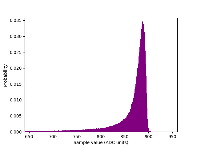
Noise distribution of a common 24V Zener diode.
It is nothing more than sampling via internal ADC on an Arduino Uno. The thing to note is the scale of the distribution. The particular diode we used was very noisy indeed, and they vary tremendously even within the same batch. That’s just randomness at play!
If we ignore any sample correlation for illustrative purposes, the min. entropy can be easily approximated via the standard $ -\log_2(p_{max})$ formula. Hence $H_{\infty}$ ~ 4.8 bits /sample, with no hardware signal amplification whatsoever. And sampling at 10kSa/s results in approximately 48kbps of raw generated entropy. Correlations, extractions, transmissions and other processing will of course reduce this rate, but it forms a basic fag packet estimate.
This entropy sample is from a development run of the Zenerglass.