Electrical details
Essentially, this is a Chekhov circuit operating off a common 9V battery. 9V is just sufficient bias to induce avalanche in the particular Zener diodes we use (BZX79-8V2). Not a lot, but enough as they tend to be ~9.4Vish when new. Mata Hari’s unique selling point is simplicity and reliability. Just four primary components for the source, and a 9V battery. A similar arrangement as in our second Dangerous Box.
The 40 uA reverse bias current is buffered to an output impedance of ~ 65 Ω by the FDN337N[1] MOSFET transistor acting as a voltage follower. R2 is sized to only pass 1 mA allowing good battery run time. There is a voltage meter in the kit to verify the bias.
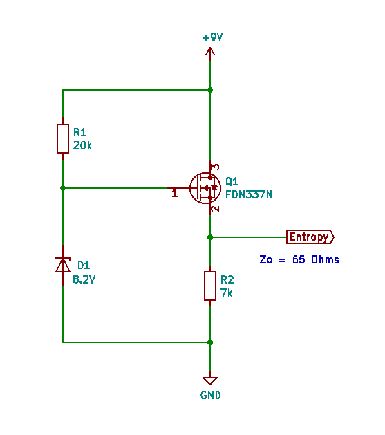
Source schematic.
The following SPICE analyses show that this buffer configuration works well for the estimated 20 mVpp Zener noise sampled at 10 kSa/s. We have used an internal SPICE model (RSR030N06) that has a roughly equivalent on resistance (0.08 Ω)…
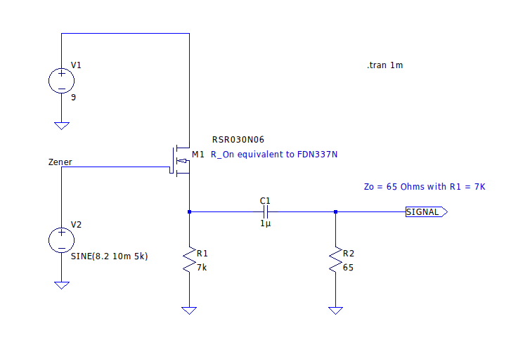
Spice analysis schematic for output impedance.
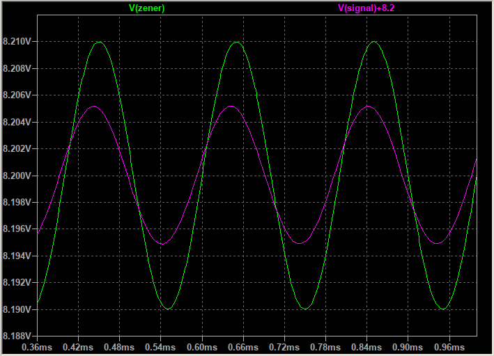
Spice analysis waveforms showing 50% signal degradation for R2 = 65 Ω.
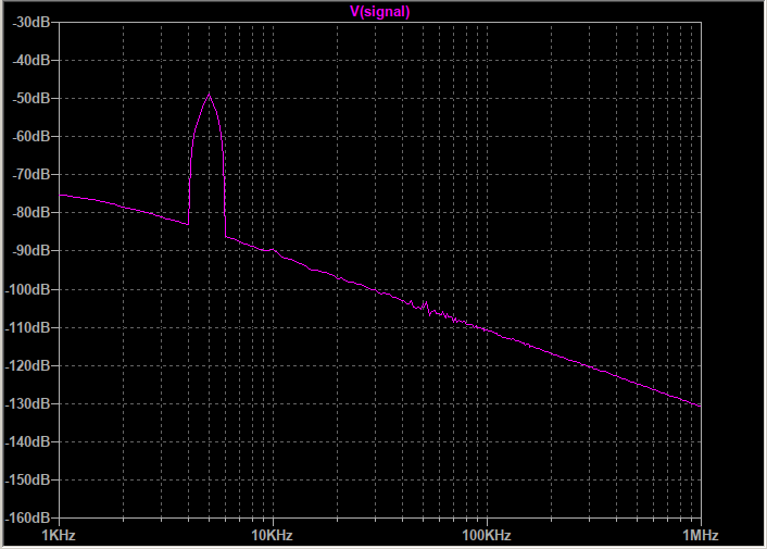
Clean FFT analysis of voltage follower for R2 = 65 Ω.
The unamplified entropy signal is then sampled by an Arduino Nano, after suitable AC input biasing. The signal is small but stiff, so R3/R4 are sized to provide a 0.55 V DC operating point when fed by the Nano’s 3.3 V output. This allows us to use the Nano’s internal 1.1 V ADC reference. In terms of our (ε, τ) sampling methodology, ε = 1.1 mV. That’s better than some oscilloscopes and ideal for measuring the small avalanche noise. A raw 100 MB file of Nano samples is available in the Related Files section.
Since the kit is designed for use with a PC/laptop, the sampling circuit is powered via the USB connection, preserving battery life.
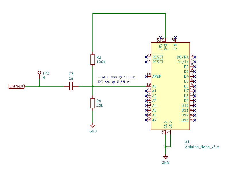
Sampling circuit schematic.
Surface mounted components keep the PCB mainly within the Nano’s footprint. The all important Zener diode (D1) can be seen clearly on this slightly older type:-
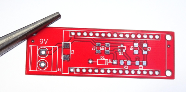
Unpopulated PCB. Type 2.
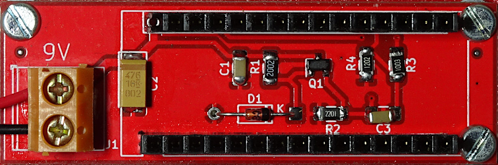
Populated PCB. Type 2.
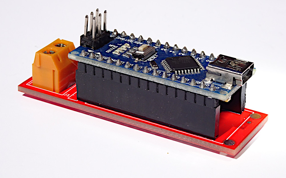
Final PCB assembly.
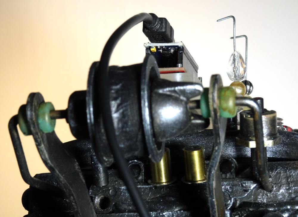
Mata Hari on the test stand.
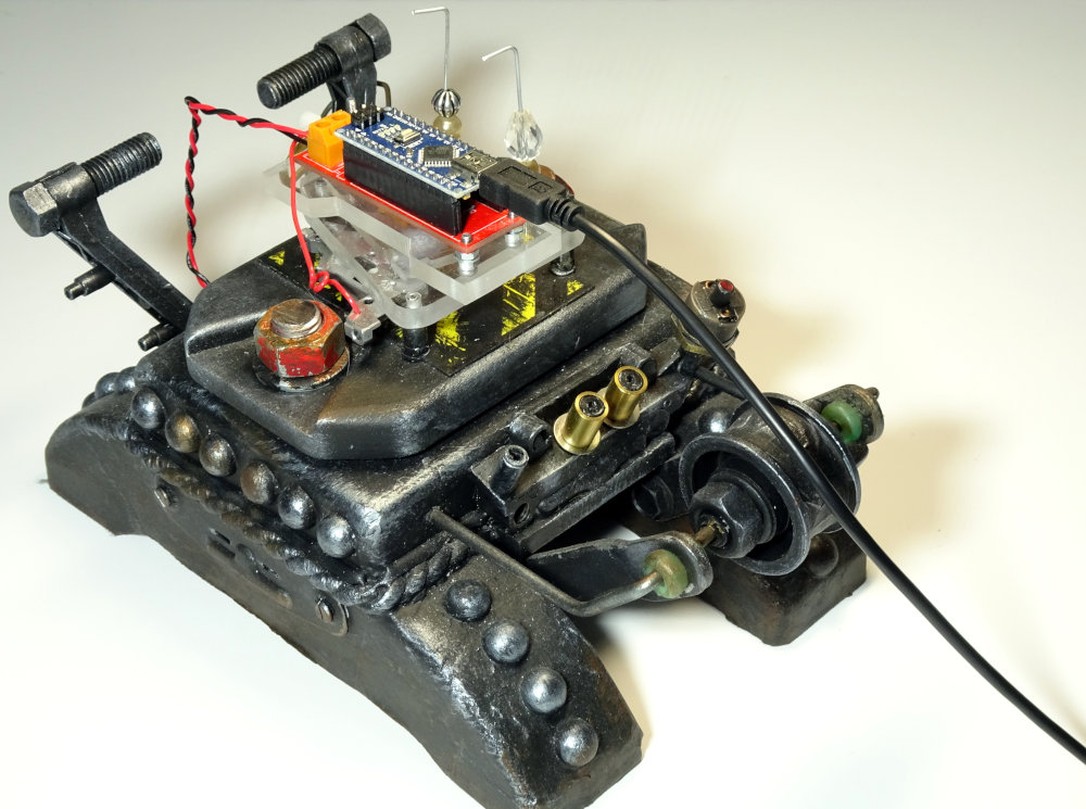
Mata Hari on the test stand.
And it produces a raw internal signal something like this:-
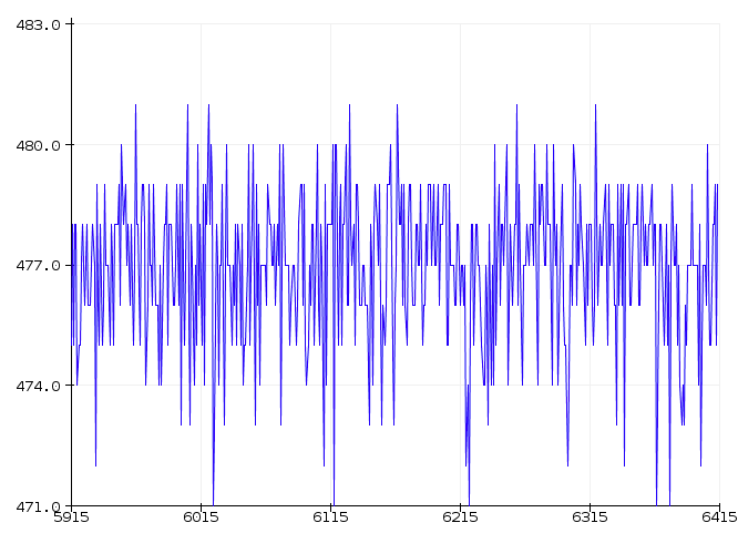
Raw entropy signal (ADC units).
The raw signal isn’t a whopper, but it’s enough as shown by this histogram (raw-signal mod 256)…
ADC Value Char Occurrences Fraction
152                1   0.000000
181   �            1   0.000000
192   �            1   0.000000
204   �            1   0.000000
208   �           20   0.000000
209   �          274   0.000003
210   �         2089   0.000021
211   �        13024   0.000130
212   �        56303   0.000563
213   �       192610   0.001926
214   �       566547   0.005665
215   �      1376060   0.013761
216   �      3126287   0.031263
217   �      5938679   0.059387
218   �     10598413   0.105984
219   �     16428580   0.164286
220   �     22322185   0.223222
221   �     21706092   0.217061
222   �     12882807   0.128828
223   �      4106598   0.041066
224   �       648346   0.006483
225   �        33240   0.000332
226   �         1664   0.000017
227   �          170   0.000002
228   �            7   0.000000
252   �            1   0.000000

Total:     100000000   1.000000
The signal ranges across 26 ADC units or approximately 29 mVpp (100 million samples @ 10 kSa/s. This sample set is available in ‘Related files’). That’s equivalent to 4.7 bits of binary range, or a Signal-to-quantization-noise ratio (SQNR) of 28 dB. But it can’t be used as is…
Notes:-
- Any small signal N channel MOSFET will do. Just find one, e.g. 2N7002 :-)