Mechanical details
In no particular order,
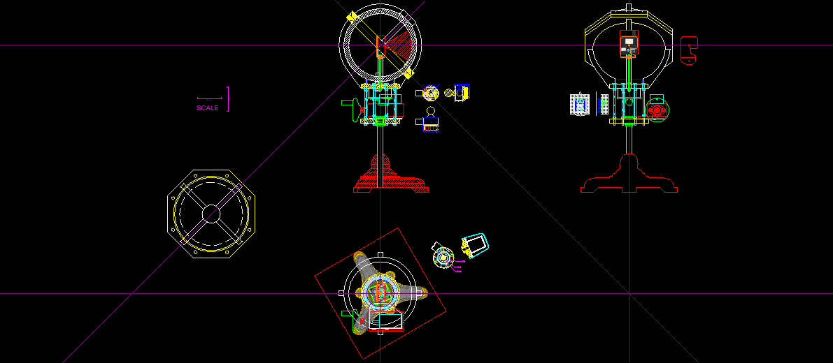
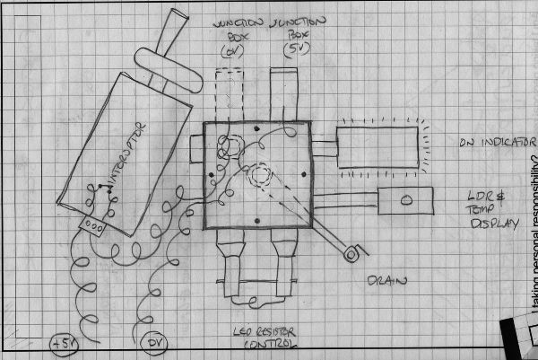
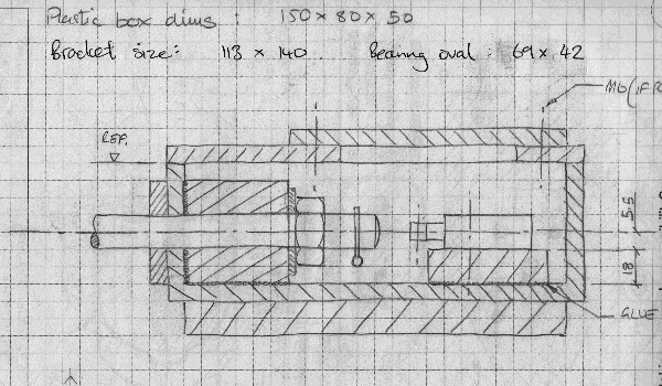
Technical Drawing.
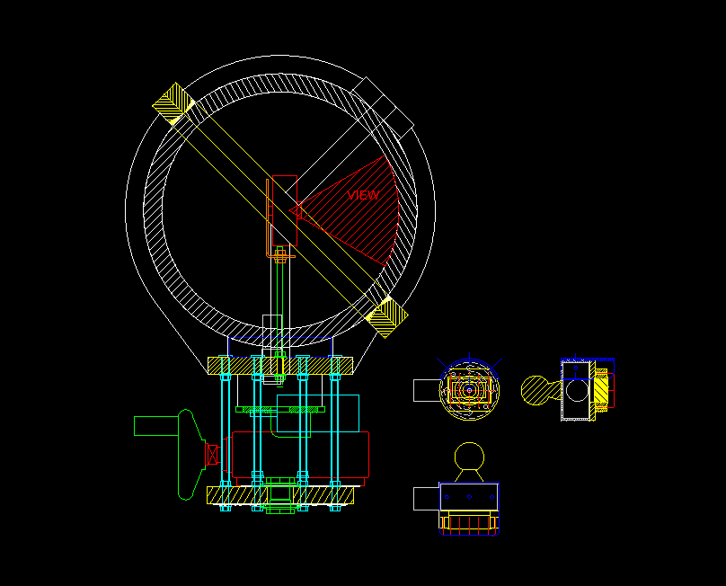
Technical Drawing of the integrating sphere and camera mount.
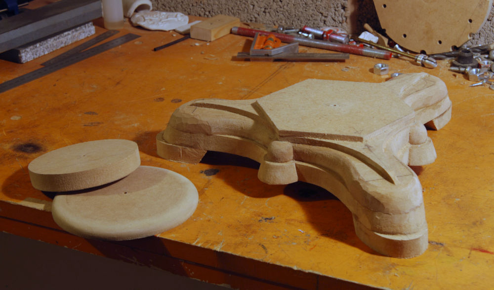
Carving the base.
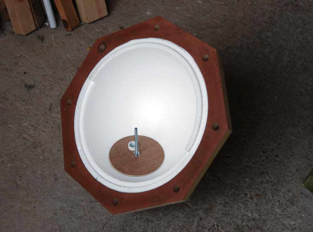
Inside the integrating sphere, showing the camera mount.
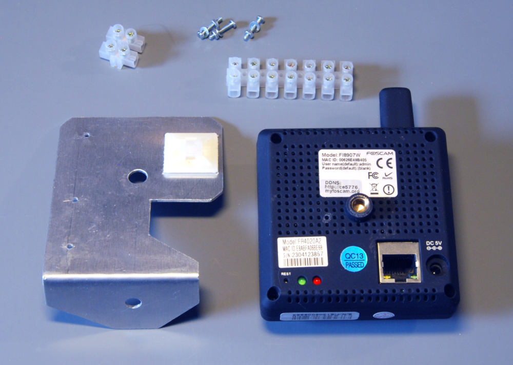
Mounting for the camera.
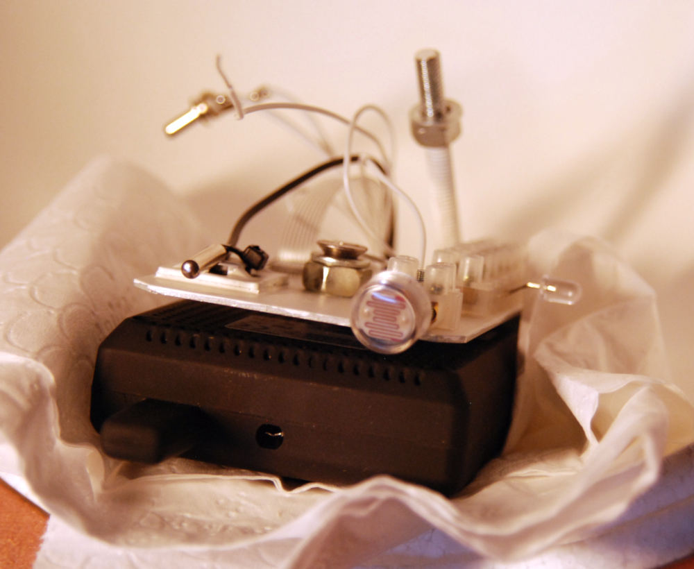
Sensors and LED mounted to rear of camera.
In the above, you can see (going left to right) a digital temperature sensor, the ORP-12 photo-resistor for light measurement and the LED providing the sphere’s illumination. You will also notice the hole in the top of the camera. That is where the camera’s photo-resistor was, after having been removed.
Nothing remarkable for the power supply, just a standard 1A 7805 linear regulator on a heat sink. Additional heat shedding is provided by the full width copper cooling coil. The instrument will get it’s bulk power from a regulated 13.8V power supply. Notably though, there is the fluidic inductor, which is the spiral yellowy green component containing a magnetic smoothing bubble for further ripple suppression. This effectively acts as a large hydraulic ferrite bead providing an additional 35dB common mode rejection.
There are no indicator lights as there will be a dedicated full instrument ON indicator.
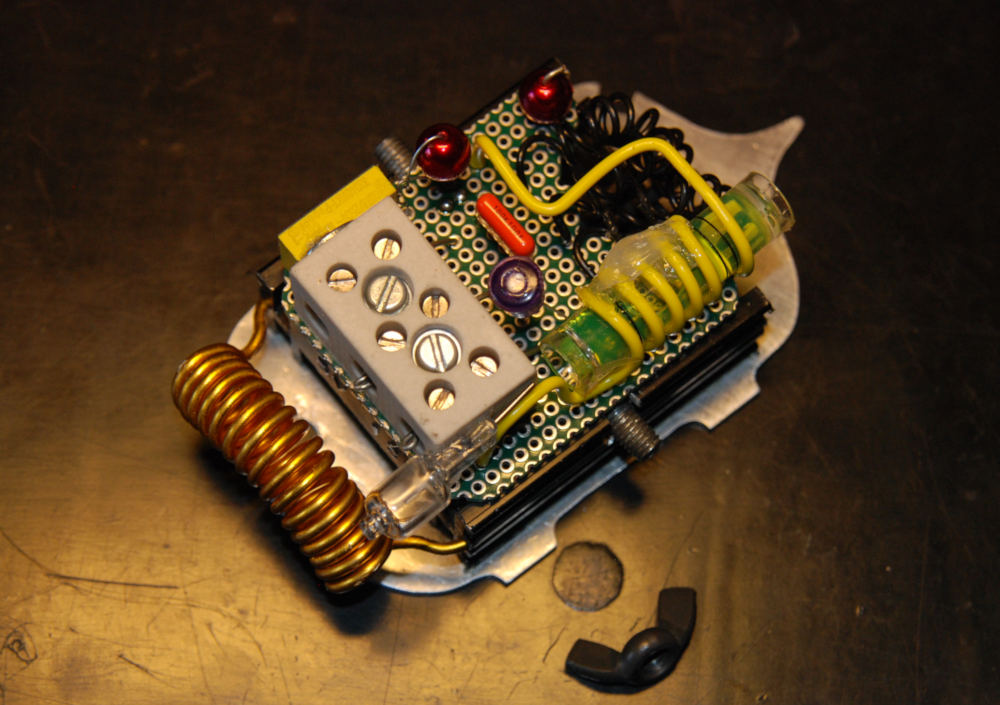
The voltage regulator.
There are three or four areas that require monitoring and /or adjustment:-
- The temperature within the integrating sphere.
- The value of the light dependant resistor to monitor illumination levels.
- Adjustment of the series resistor that controls the LED generating the illumination.
- There will also be some sort of a visual ON indicator, which may be the transparent plastic cylinder on the right of the image. Safety is paramount and nobody wants to put their paw into a running integrating sphere.
Various sensors.
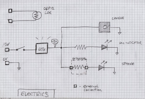
Electric layout.
Of course the Photonic Instrument has to be able to be turned on and off. So the simplest and easiest method is to build a hand wheel operated switch. At least no one will accidentally turn the instrument off with a casual swipe of the paw.
On/off switch concept.
This is the inside of the switch, where a smaller blue industrial limit switch can be seen at one end. The M12 nut is fixed, so as the M12 studding is rotated, it moves against the roller lever attached to the limit switch. The industrial dia.12 bearing on the outside of the box keeps the shaft running freely, albeit with an annoying squeak. The issue of the squeaking can be solved by greasing the shaft.
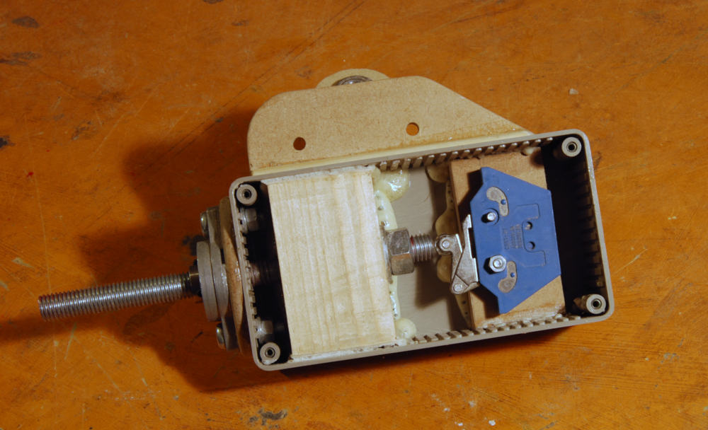
On/off switch
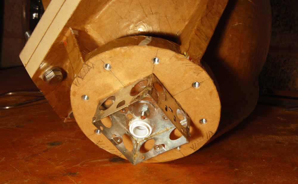
Access to the inside of the integrating sphere will be though this port and junction box. Various instruments and things will be connected to the junction box, as is the fate of all junction boxes.
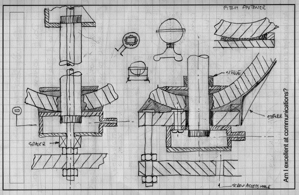
The design of the thing we call the polyclamp.
One of the trickiest parts of the Photonic design was how to attach the polystyrene integration sphere to the rest of the instrument, especially the wiring port for the electronics. Delicate 20mm thick polystyrene spheres and flat 18mm MDF do not easily fit together. The solution was a clamp made from a plastic screw lid. The lid will be glued and bolted to the MDF, with a support rod for the camera and a length of 20mm plastic conduit passing though, as:-
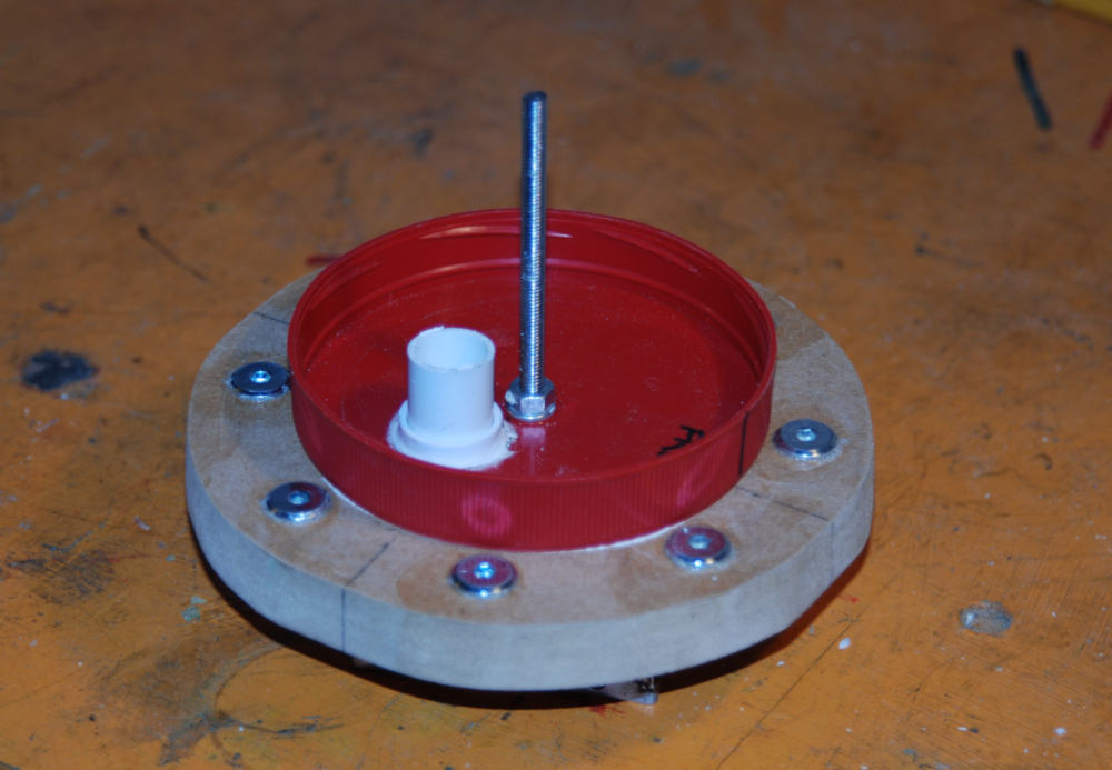
The thing we call the polyclamp.
A circular wooden plate will then be screwed down over the sphere from the inside to hold it. This will only be temporary until the joint is fully paper mâchéd. Adhesion will then suffice. The eight silver inserts around the red lid are M6 screw inserts for connecting the clamp to the next level of the support structure. The M6 rod for the camera mount can be seen dead centre within the sphere. The white 20mm conduit passing through the poly clamp can also be seen. The camera wiring will pass through this tube.
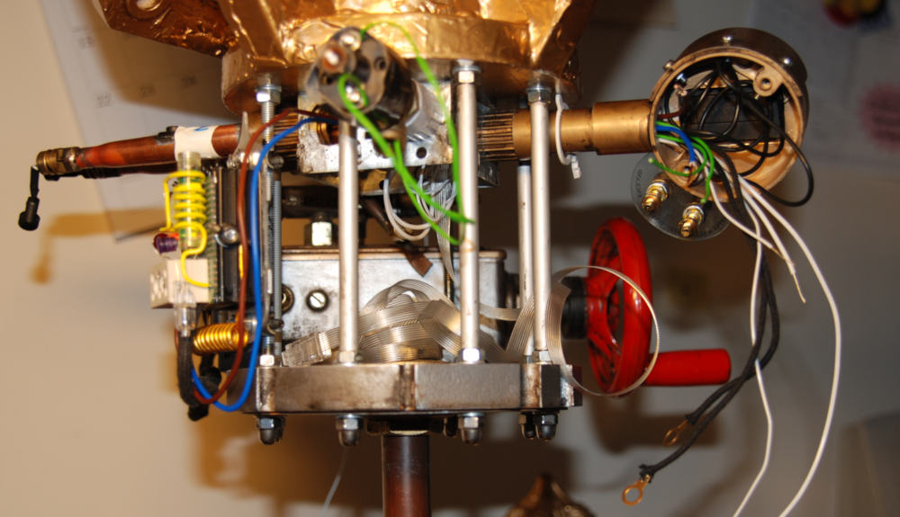
Electrical access port to the integrating sphere.
Thing is, there’s a lot of white wires that confusingly all look the same. Perhaps a different strategy might be used in the future on another white integrating sphere. The connection for the external LED dropper resistor can be seen on the extreme LHS at the end of the horizontal copper tubes. The RHS circular feature is the mounting for the thermometer and photo resistor measuring point. A multi meter can be plugged into 4mm banana sockets to measure the resistance, and therefore indirectly the light level inside the integrating sphere.
The power supply has been tested using a 13.8V general PSU without incident (no serious fires).
General wiring up and testing.
“It’s alive!”